I was just wondering: when did the term “roll center” become something that even ordinary car enthusiasts started hearing about?
When I first became interested in suspension, I was at the level of, “What’s the difference between a spring and a damper?” So, naturally, I had no idea what a roll center was.
These days, though, I come across the term “roll center” fairly often.
The concept of a roll center isn’t particularly difficult.
But if you simply explain it by saying, “The roll center is the center of the car’s roll,” most people won’t really have any idea what that means.
To understand it properly, you really need to use diagrams.
So today, I’d like to explain the roll center in a simple way, using diagrams.
But, sorry, I need to make one excuse first.
I don’t want you to get all the way to the end and complain, “Hey! That wasn’t simple at all!”
So let me make my excuse right at the beginning.
There are plenty of highly detailed explanations of roll centers out there.
And if you can read one of those explanations and understand it correctly, then you probably don’t need what I’m about to write at all.
You don’t need to read this.
However, I think there are also people who read those technical explanations and still don’t quite get it.
Even explanations that deal with highly technical subjects can be written in a surprisingly clear and approachable way.
But cars are complicated things, so there will always be people who understand them and people who don’t.
As someone like me, who knows practically nothing about physics and comes from a humanities background, there are plenty of times when I find myself thinking, “Could you explain this part a little more clearly?”
So that’s what I’m going to try to do this time: explain it in an even more straightforward way, in my own words.
Anyway, enough with the long introduction.
How to Find the Roll Center
Let’s start by figuring out how to find the roll center.
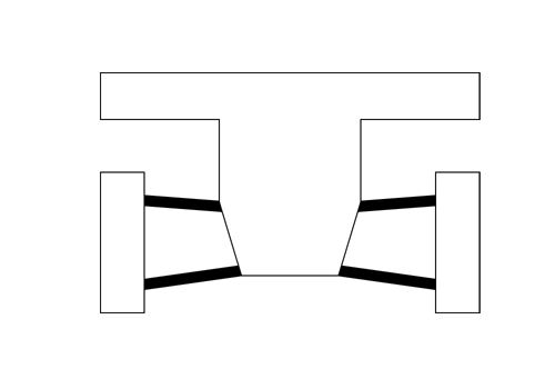
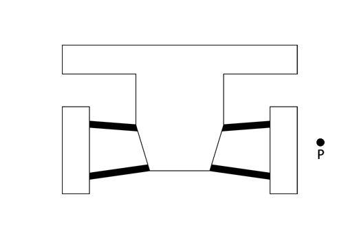
Now, let’s say we have a double-wishbone suspension with geometry like this.
First, draw a line extending along the upper arm on one side.
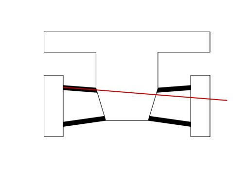
Then, do the same with the lower arm.
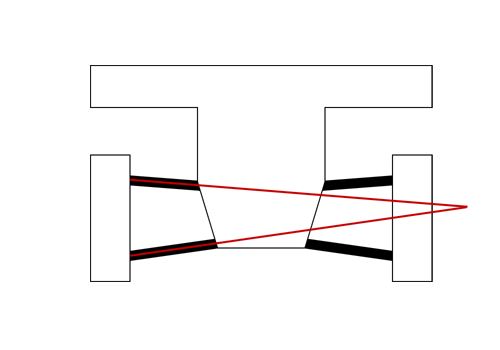
The point where those two lines intersect is point P.
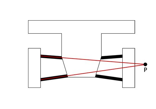
Next, draw a line connecting point P to the center of the tire contact patch.
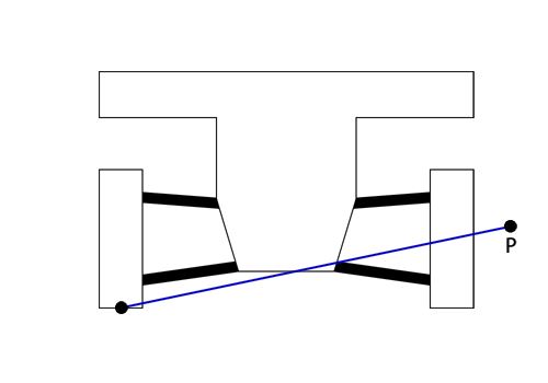
Then, do the same thing on the suspension on the opposite side.
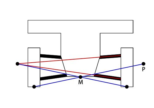
The point where the two blue lines intersect, point M, is the roll center.
Therefore, point M is the instantaneous center of rotation for the car’s roll motion.
Now, if all you’re going to do is memorize this, I’m pretty sure even a kid could do it.
But the important thing is understanding why it works this way.
If you don’t understand the reasoning behind it, you’ll forget it as soon as you’ve memorized it.
Once you understand, “Oh, I see! That’s why the roll center ends up right here!” you won’t forget it so easily.
Why Point P Is the Instantaneous Center
So now, let’s think about why the roll center is determined this way.
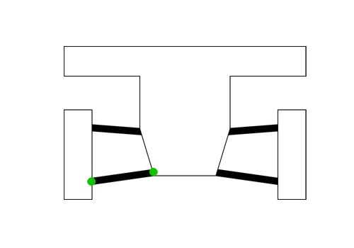
First, let’s focus on the mounting points of the lower arm.
The ones marked with the green circles.
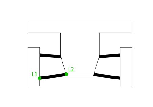
Let’s call the hub-carrier-side mounting point L1, and the chassis-side (body-side) mounting point L2.
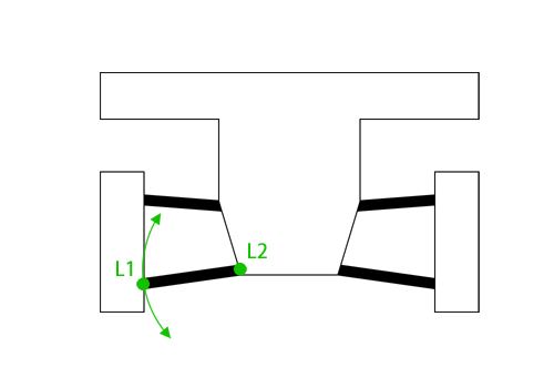
Now, if we fix point L2 in place, we can see that point L1 rotates around L2.
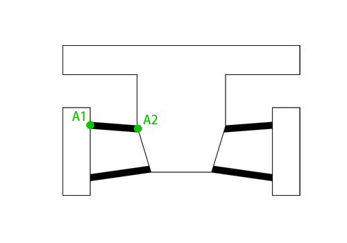
The same thing applies to the upper arm. If we call its two mounting points A1 and A2,
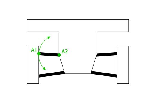
we can see that A1 rotates around A2.
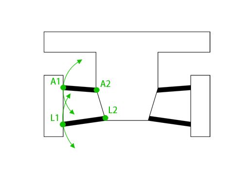
When the wheel moves, the upper and lower arms move at the same time.
So, basically, it looks like this.
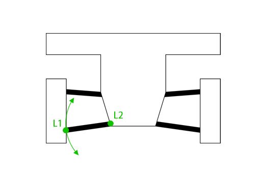
Now, let’s take another look at the movement of the lower arm.
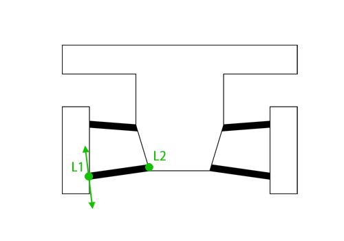
I want you to imagine the exact instant when the lower arm starts to move.
I’m not talking about after it has already moved some distance. I’m talking about the very instant just as it starts to move.
At that instant, which direction is point L1 trying to move in?
It’s trying to move in the direction shown by the arrow.
In other words, it’s moving perpendicular to the lower arm.
If you’re thinking, “Wait a minute. L1 moves along a circular path around L2, so how can you say it moves in a straight direction?” you’re absolutely right to think that.
But we’re only thinking about the very instant when the motion begins, so bear with me and think of it that way.
This is the key point of today’s discussion, so if you’re still not quite getting it… hang in there.
In other words,
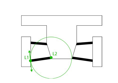
at the very instant a point begins moving along a circular path, its direction of motion is along the tangent to the circle, as shown by the arrow.
But if we look at this the other way around, we can say that if the initial direction of motion of point L1 is the direction shown by the arrow,
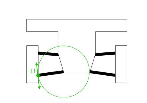
the circular path could, of course, be a circle like this.
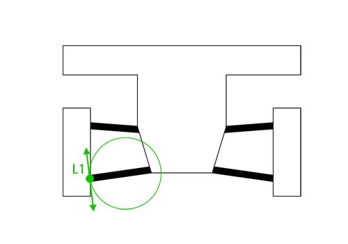
But simply knowing that “the initial direction of motion of point L1 is in the direction shown by the arrow” also means that the circle could be smaller, like this,
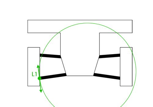
or it could be much larger.
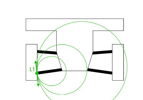
Regardless of how large or small the circular path is, we know one thing for certain: the initial direction of motion of point L1 is the direction shown by the arrow.
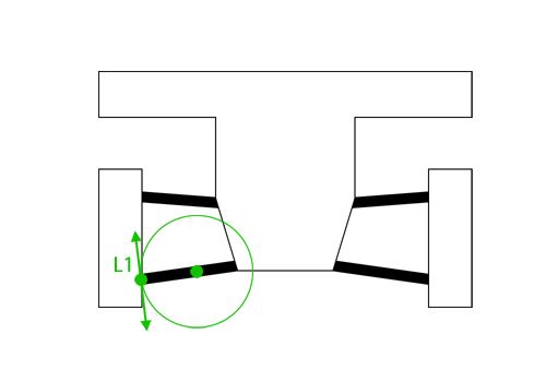
So, for example, if we have a small circle, its center would be somewhere around here.
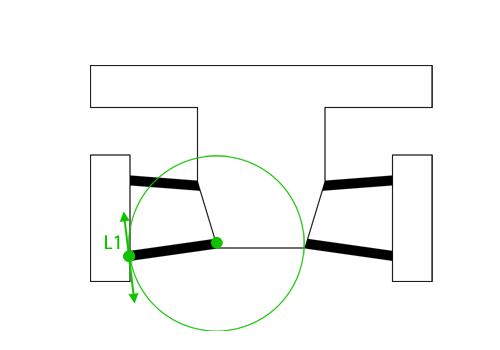
For a medium-sized circle, its center would be somewhere around here.
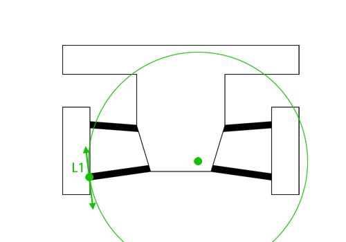
And for a large circle, the center would be somewhere around here.
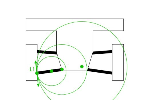
Now, if we only consider the centers of these circles,
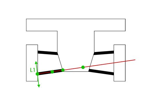
we can see that regardless of whether the circle point L1 is trying to follow is large or small, its center must always lie somewhere along the line extending from the lower arm.

The same thing applies to the upper arm.
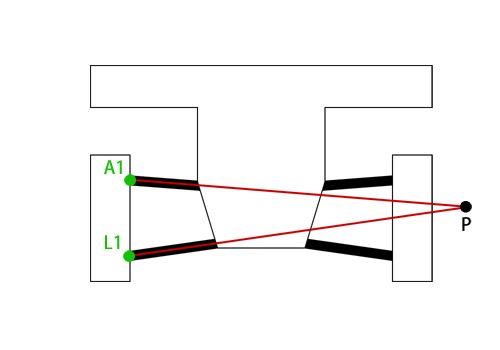
So when points L1 and A1 try to move at the same time, the only center of rotation that can satisfy both movements simultaneously is point P, where the extended lines of the upper and lower arms intersect.
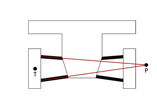
Now, points L1 and A1 are fixed to the tire (hub carrier).
So, if we call the center of the tire point T,
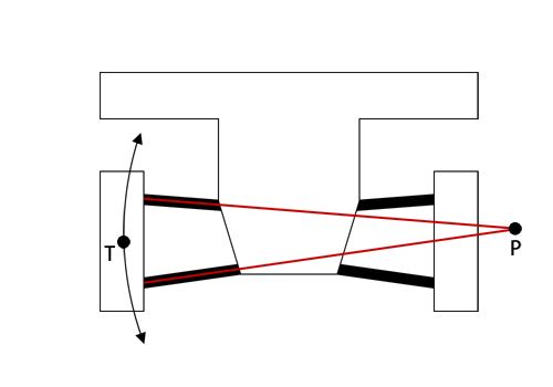
point T is, at that instant, trying to move along a circular path centered at point P.
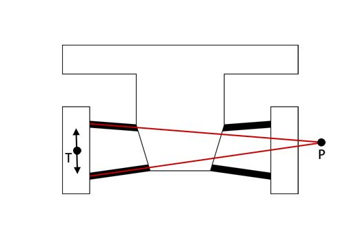
Strictly speaking, though, we’re only talking about the very instant when the motion begins, so in terms of the direction in which it is trying to move, it is still the direction shown by this arrow.
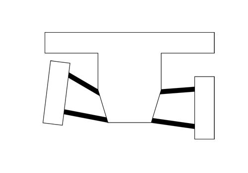
Why the Instantaneous Center Keeps Moving
Why do we only consider that very instant when the motion begins?
Because if the suspension moves through its stroke like this,
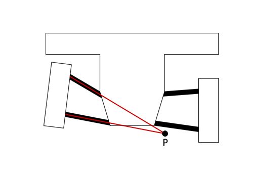
the intersection point P of the extended upper and lower arm lines moves to a different location.
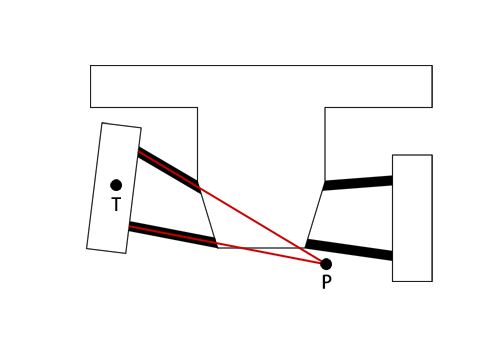
That means point T is now trying to follow a circular path centered on a different point than before.
As the tire moves up and down, the center of the circle continuously changes. So points L1 and A1 don’t actually follow simple circular paths around one fixed point. Instead, their path has continuously changing curvature as the instantaneous center moves.
Anyway, the important point is that the center of the circle is constantly moving.
From Point P to the Roll Center
So far, we’ve been looking at the movement assuming the car is suspended in mid-air and the body itself is fixed.
But when we think about roll motion, there is one more movement we need to consider.
That is the circular motion around the center of the tire contact patch (strictly speaking, the center around which the tire tilts).
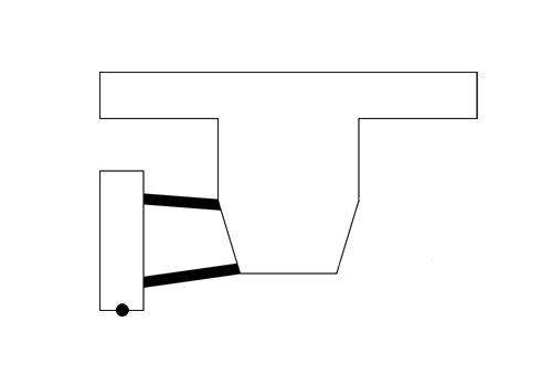
From here on, I’ll show only one side of the suspension to make the diagrams easier to see.
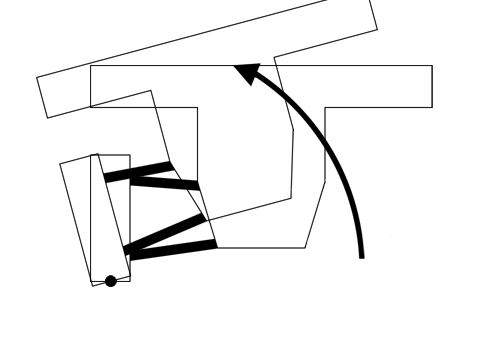
The car can move around a point near the tire’s contact patch like this,
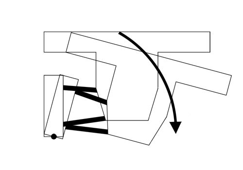
or like this.
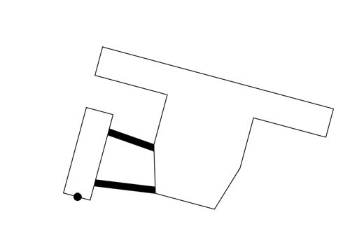
And even from a position like this,
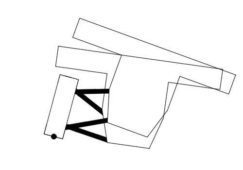
the car can move further like this as the suspension goes through its stroke.
See what I mean?
One, two, one, two… it moves like that, right?
However, as we already spent quite a while explaining, we know that the instantaneous center of rotation during suspension movement is point P.
So, regardless of how the body itself moves, all we really need to think about is how point P is trying to move.
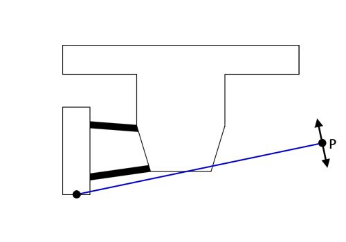
In this case, point P is trying to move in the direction shown by the arrow.
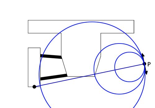
But, again, if we’re only considering the very instant when the motion begins, the center of that circular path isn’t necessarily the center of the tire contact patch. It can be located anywhere along the line connecting the center of the tire contact patch and point P.
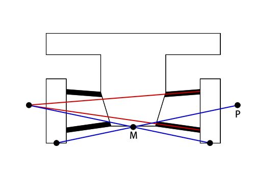
Roll motion is the combination of the tire’s movement around point P (the circular motion of points L1 and A1) and the body’s movement around the center of the tire contact patch (the circular motion of point P).
Therefore, if we find the point that simultaneously satisfies both of these circular motions, we can see that this point is the roll center.
So, when we perform the same process on both sides, the point M where the two blue lines intersect is the roll center.
To properly understand this kind of geometric movement, you really need to explain it using diagrams.
Trying to explain it without diagrams is not much different from not explaining it at all.
In the same way, if you can’t draw a diagram to explain something, that probably means you don’t fully understand it yet.
So, before anything else, I’d like to start by making sure I understand it correctly.
Once you properly understand the roll center, you can also see that, for example, if you design the suspension geometry so that the two points P on the left and right sides overlap, you can create a car where the tires’ camber relative to the ground does not change at all as the car rolls.
You can also understand what it actually means to arrange the upper and lower arms in parallel.
But no matter how smart you are, it’s important to draw the diagrams yourself.
So, if you’re having trouble understanding something, it’s even more important to actually draw the diagrams and think it through yourself.
Anyway, that’s it for this long, completely pointless ramble about something that isn’t going to do you any good. Haha.