If you’ve ever driven on a racetrack, there’s a good chance this question is always sitting somewhere in the back of your mind:
“What’s the fastest way through this corner?”
In Japan, there’s a legendary professional racing driver named Motoharu Kurosawa. If you ask who has had the greatest influence on circuit driving in Japan, his name is almost always one of the first to come up.
In one of his books, he wrote: “Break a corner down into a series of radii, connect them all with perfect circles, and the result is the ideal racing line.”
Coming from someone everyone just calls “Gan-san,” it’s easy to see why this became the accepted wisdom for so many years.
Today, however, it seems we’ve learned that the ideal racing line isn’t quite a perfect circle after all. Part of that is probably due to how much cars and tires have evolved over the years. In many situations, a slightly V-shaped line actually turns out to be faster.
So why is that? Why can a perfect circular line be slower than the fastest racing line? Over the years, I’ve heard all kinds of explanations. “The distance is shorter.” “You can get back on the throttle earlier.” Those explanations aren’t necessarily wrong. But personally, I had never come across one that really made me think, “Ah… now I finally understand.”
Then, not long ago, a friend of mine from a Japanese social network for car enthusiasts — a blogger who goes by Tatsu — introduced an idea from *The Perfect Corner* by Adam Brouillard (Paradigm Shift Driver Development, 2015), an English-language technical book, that might finally explain this long-standing mystery.
If the idea is correct, it provides a remarkably clear way of understanding why the fastest racing line is, in fact, the fastest.
This doesn’t mean the fastest line around each circuit suddenly changes. A fast line is still a fast line. What changes is the way we think about why that line is fast. That may prove useful for driving instructors, gymkhana competitors, engineers studying vehicle dynamics, or developers working on autonomous vehicles that need to operate near the limits of tire grip.
And for the rest of us amateur drivers… understanding why the fastest racing line is the fastest is simply fascinating.
So, partly to organize my own thoughts, I’d like to walk through the idea here.
The original sources are listed below.
The concept comes from the English-language technical book The Perfect Corner, which Tatsu later explained in Japanese through a series of blog posts. Now I’m taking that explanation, simplifying it in Japanese… and translating it back into English again. Quite an impressive trip around the world. Unfortunately, it earned exactly zero frequent flyer miles. Haha.
The Perfect Corner
Optimizing the Racing Line Through a 180° Hairpin — Part 1
Optimizing the Racing Line Through a 180° Hairpin — Part 2
Optimizing the Racing Line Through a 180° Hairpin — Part 3
Optimizing the Racing Line Through a 180° Hairpin — Part 4
Optimizing the Racing Line Through a 180° Hairpin — Part 5
Optimizing the Racing Line Through a 180° Hairpin — Part 6
Optimizing the Racing Line Through a 180° Hairpin — Part 7
Optimizing the Racing Line Through a 180° Hairpin — Part 8
Optimizing the Racing Line Through a 180° Hairpin — Part 9
Optimizing the Racing Line Through a 180° Hairpin — Part 10
Optimizing the Racing Line Through a 180° Hairpin — Part 11
Optimizing the Racing Line Through a 180° Hairpin — Part 12
Optimizing the Racing Line Through a 180° Hairpin — Part 13
To keep this article easy to follow, I’ll focus on the big picture rather than every mathematical detail.
If you’re looking for a rigorous treatment, I highly recommend reading Tatsu’s articles.
So what exactly is this idea? In short, it comes down to three key points.
1. Represent the change in velocity — from corner entry to corner exit — as a vector.
2. The faster you can complete that vector change, the faster you can negotiate the corner.
3. To make that happen in the shortest possible time, you should use as much of the tire’s available grip as possible in the same direction as that vector change, while staying on the limit of the tire’s traction circle.
That may still sound a little abstract. So let’s start by looking at what it actually means to represent the change in velocity as a vector.
Let’s begin with the diagram below.
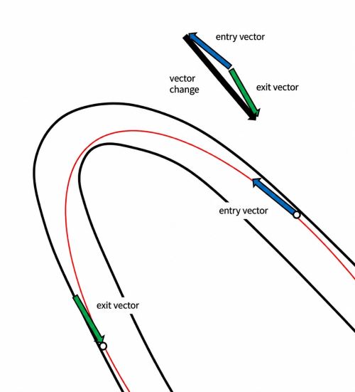
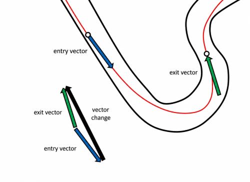
The blue arrow represents the velocity vector at corner entry, and the green arrow represents the velocity vector at corner exit.
First, we compare those two vectors. Doing so gives us the required vector change between corner entry and corner exit — representing how the car’s velocity vector must change.
That vector change is the black arrow.
Now we know exactly what that vector change looks like, from corner entry to corner exit.
The central idea is simple: the faster we can accomplish that vector change, the faster we can get through the corner.
Of course, tire grip is limited. A car can only operate within that limit.
So the obvious question becomes: how should we use the available grip to accomplish that vector change as quickly as possible?
Take a look at the next diagram.
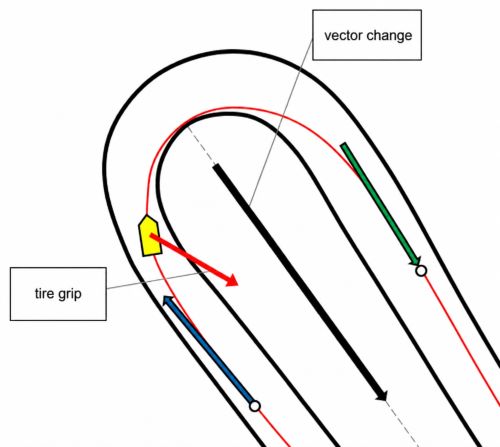
Imagine the car is at this point in Turn 2 at Takasu Circuit— a race track in Japan.
At this moment, the driver is trail braking — gradually releasing the brake pedal while steering into the corner. That means the tires are generating both longitudinal and lateral forces simultaneously.
In other words, the available grip is being used diagonally.
Now focus on two directions: the direction in which the tire is generating force (the red arrow), and the direction of the required vector change (the black arrow).
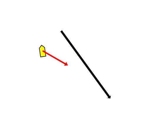
Now let’s resolve the tire force into two components: one parallel to the black arrow, and one perpendicular to it.
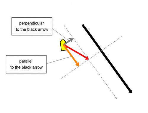
Once we do that, something very important becomes clear. We can now see how much of the tire’s available grip is actually being used to produce that required vector change.
This is it. This is the important part.
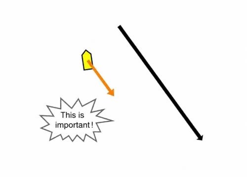
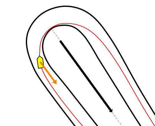
If the goal is to complete that vector change in the shortest possible time, then we should use as much of the tire’s available grip as possible in the direction of that change.
The orange arrow represents exactly that component.
The larger the orange arrow is, the more effectively the tire is contributing to that vector change.
But — hold on a second.
Suppose we’re driving through a 180-degree hairpin.
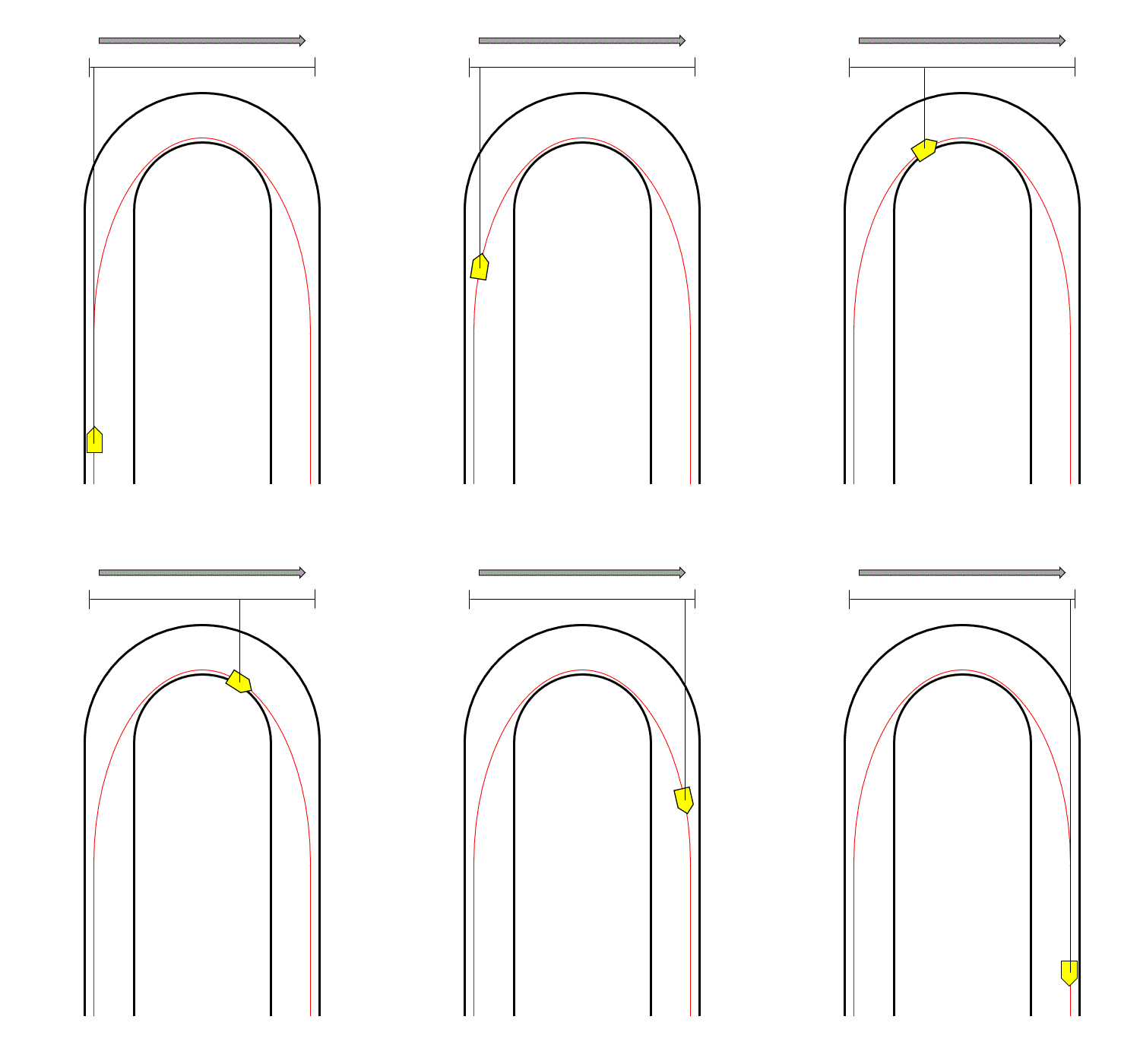
Take a look at the following animation.
The required change in velocity between corner entry and corner exit looks like this. From the perspective of the black arrow, the car’s velocity travels “out” and then “back.”
The goal is to complete that vector change as quickly as possible.
However, there’s one obvious problem. The car also has to move sideways in order to get around the corner.
(Note 1: Here, “parallel” and “perpendicular” refer to the direction of the black arrow — the direction of the required vector change — not the car’s own longitudinal and lateral directions.)
(Note 2: To match Tatsu’s original articles, from this point onward I’ll refer to the direction of the black arrow — the direction of the required vector change — as the corner centerline direction.)
Because the car must also move sideways, it can’t devote all of the tire’s grip to the corner centerline direction. Some grip must always be reserved to generate the sideways motion needed to get around the corner.
The important point is this: once we’ve allocated the minimum grip required for that sideways motion, we should devote as much of the remaining grip as possible to the corner centerline direction.
And that finally brings us to the racing line itself.
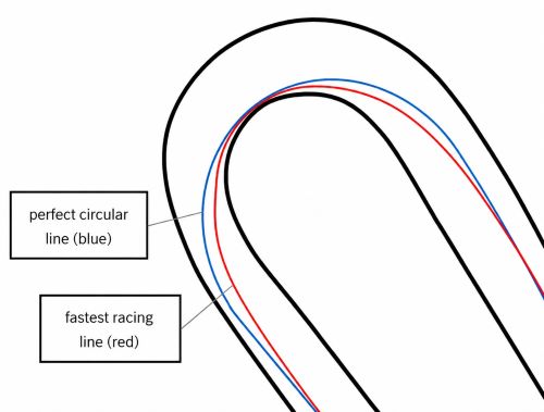
Suppose the line we’ve been discussing is the fastest racing line. Now let’s compare it with a perfect circular line.
The blue line in the diagram represents the circular line.
Imagine the car is at the same position as before. On the fastest racing line, the tires are using a relatively large portion of their available grip for deceleration while still generating the cornering force needed to follow the line.
On the circular line, however, the tires are using essentially 100% of their available grip for cornering at that point. That leaves little or no grip available for deceleration.
Now let’s resolve the tire forces into components once again — this time using the corner centerline direction and the direction perpendicular to it.
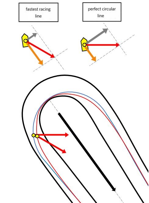
Notice what happens. The component of tire force acting in the corner centerline direction — the orange arrow — is smaller for the circular line. That means it cannot accomplish the required vector change as quickly.
In other words, it cannot complete that change in the shortest possible time.
Now let’s think for a moment about the motion perpendicular to the corner centerline.
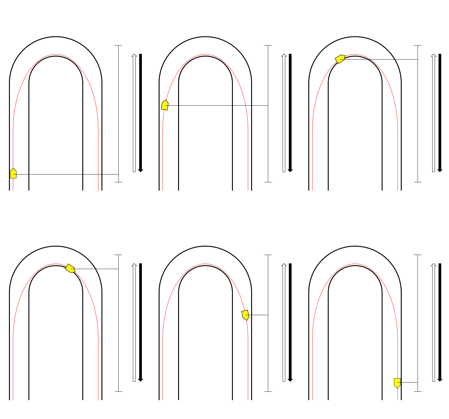
When the car is traveling down a straight, it’s obviously moving straight ahead. Relative to the corner centerline direction, its sideways velocity is zero. In the animation, that’s the car at the far left.
From there, the sideways velocity increases. It reaches its maximum near the middle of the corner. Then it decreases again. By the time the car reaches the far right, the sideways velocity is back to zero.
Incidentally, this sideways velocity happens to match the speed shown on the car’s speedometer only at the midpoint of the corner. Everywhere else, the two are different because the car is traveling in a different direction. Essentially, the car’s speed is a combination of its longitudinal speed and this sideways motion, and at the midpoint, the car is pointing directly in the direction of travel for the corner trajectory.
Now let’s return to the difference between the two racing lines. A circular line usually has a larger turning radius, allowing the car to carry more speed through the middle of the corner.
The fastest racing line, being more V-shaped, typically carries a slightly lower speed through the middle of the corner.
So why does the circular line still lose overall? The answer lies in that sideways motion.
Imagine the sideways velocity changing like this: zero → accelerate → maximum → decelerate → zero.
If the peak sideways velocity is very high, the car has to accelerate much harder to reach it — and then decelerate just as hard to bring it back to zero. That consumes tire grip.
And every bit of grip spent doing that is grip that can’t be used to accomplish the required vector change.
Think of it this way. The sideways velocity ends at zero anyway. So building up a large sideways velocity in the middle of the corner, only to eliminate it again before corner exit, is ultimately work that doesn’t directly contribute to the required change from the entry velocity vector to the exit velocity vector.
The larger that unnecessary acceleration and deceleration become, the more grip is consumed. And the more grip that’s consumed there, the less remains available to accomplish that vector change.
At last, it all made sense.
That’s why a perfect circular line can be slower than the fastest racing line.
This article has only introduced the basic idea behind this way of thinking. For the sake of clarity, I’ve intentionally kept the explanation intuitive and avoided detailed mathematical derivations or numerical examples.
Some readers may notice that I’ve simplified a few points along the way. After all, God is in the details, as the saying goes.
If you’d like to explore the theory in greater depth, I highly recommend reading Tatsu’s articles — or better yet, the original book, The Perfect Corner.